

Search this website


Product Series
TGV654

Customer Service Hotline:
Category:
燃气阀
- 产品详情
-
- Commodity name: TGV654
The TGV654 two-stage combined gas valve has been developed for use in both direct spark ignition and hot-surface ignition systems. The valve is also equipped with a pressure regulator and an electrically actuated solenoid shutoff to control the gas flow to the main burner.
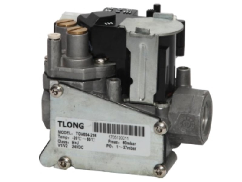
Two-stage combined gas valve TGV654
The TGV654 two-stage combined gas valve has been developed for use in both direct spark ignition and hot-surface ignition systems. The valve is also equipped with a pressure regulator and an electrically actuated solenoid shutoff valve to control the gas flow to the main burner.
Technical Data
General unit data
Model TGV654 Installation Location Any position Gas Type NG; Liquefied Petroleum Gas (with conversion kit) Gas inlet pressure Maximum 60 mbar External dimensions Refer to “External Dimensions” Inlet and outlet connections 1/2 NPT Female Ambient temperature 0~60°C Export pressure 0~37 mbar Voltage 24 Vac Frequency 50/60 Hz Electric current 0.430 amps Pressure Regulator Settings
No-go
Liquefied petroleum gas
LO 2.5–10 mbar; Hi 5–12.5 mbar
LO 11–25 mbar; Hi 20–30 mbar
Installation Instructions
Main gas connection
• To prevent deformation and/or damage to the external threads, be careful not to over-tighten the pipe fitting.
• Ensure the washer is properly positioned in the correct location.
• Ensure that the airflow direction is the same as the arrow direction on the valve body.
Pressure regulator adjustment
• Turn off all power to the system.
• When inspecting the pressure test point, loosen the screw by half a turn, then slide the tube over the nipple.
• Turn on the power and energize the main solenoid. Do not energize the HI solenoid valve.
• Remove the low-outlet cover screw, turn it clockwise to increase pressure, or counterclockwise to decrease pressure. Replace the low-outlet cover screw.
• The main solenoid and the HI solenoid are energized.
• Remove the high outlet cover screw, turn it clockwise to increase pressure, or counterclockwise to decrease pressure. Replace the low outlet cover screw.
• Turn off all power to the system.
• Remove all hoses from the test points and re-tighten the low- and high-pressure outlet cover screws.
• Turn on the system power and energize the valve.
• Use a leak detection solution or soapy water. Inspect the pressure boss screws and pressure taps for leaks.
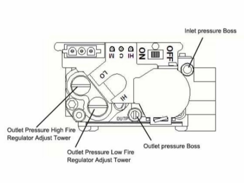
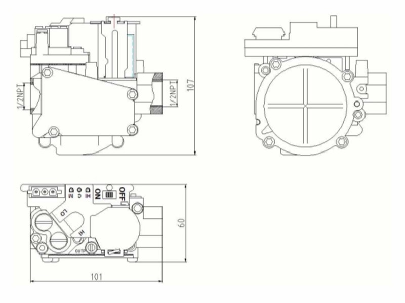
External dimensions
Dimensions (mm)
 Keywords:
- 燃气阀


Leave a Message Online
Please note: Kindly provide your email address, and our specialists will contact you as soon as possible!
Address: No. 11 Tengda Road, Cao’e Subdistrict, Shangyu District, Shaoxing City
Phone:+86-575-82052228
Fax:+86-575-82569559
Leave a Message Online


Copyright © Shaoxing Telong Electric Co., Ltd.
Website Development:China Enterprise Dynamics Shaoxing