

Search this website


Product Series
TGV725

Customer Service Hotline:
Category:
燃气阀
- 产品详情
-
- Commodity name: TGV725
The TGV725 gas combination valve is specifically designed for commercial heating boilers, condensing boilers, and premix burners. It is widely used in gas-fired boilers across a variety of applications, including hotels, schools, hospitals, government facilities, and district heating systems.
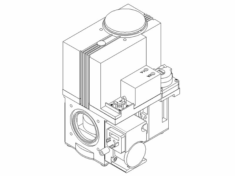
Gas Combination Valve TGV725
The TGV725 gas combination valve is specifically designed for commercial heating boilers, condensing boilers, and premix burners. It is widely used in gas-fired boilers across a variety of applications, including hotels, schools, hospitals, government facilities, and district heating systems.
Use
• The compact design makes this valve suitable for installation in modern commercial boilers and heating equipment.
• The DBI system is specifically designed for gas-fired equipment and is used for igniting the main burner.
• The servo pressure regulator provides stable outlet pressure.
• The main gas flow throttling valve adjusts the gas-to-air ratio to 1:1.
• 2 shut-off valves.
• Servo pressure regulator.
• Inlet/outlet pressure test points.
• All adjustments can be made at the top of the valve.
• A fine filter screen is installed at the inlet.
• Parallel displacement adjuster.
• The mixing regulator is equipped with a gas pressure test point.
• Adjustable gas flow.
• Pressure switch for preventing backfire under low-pressure conditions.
Precautions
To ensure the safety of operators and their working environment, the following precautions must be observed: Do not open or modify the valve without authorization!
• All operations (installation, configuration, maintenance, etc.) must be performed by qualified professionals.
• Before performing any wiring modifications on equipment equipped with the TGV725 valve, all power connections to the valve must be disconnected.
• To prevent electric shock, the terminal must be equipped with adequate protective measures.
• Verify that the circuit is operating normally.
• Drops or vibrations can compromise the safety performance of valves. Even if they appear undamaged, they must not be reinstalled or put back into service.
• Ensure compliance with national safety regulations and procedures.
Setup Precautions
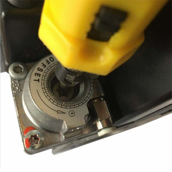
Parallel displacement regulator for adjusting the air/gas ratio
• Check the inlet and outlet pressures provided by the pressure taps.
• Remove the protective cap.
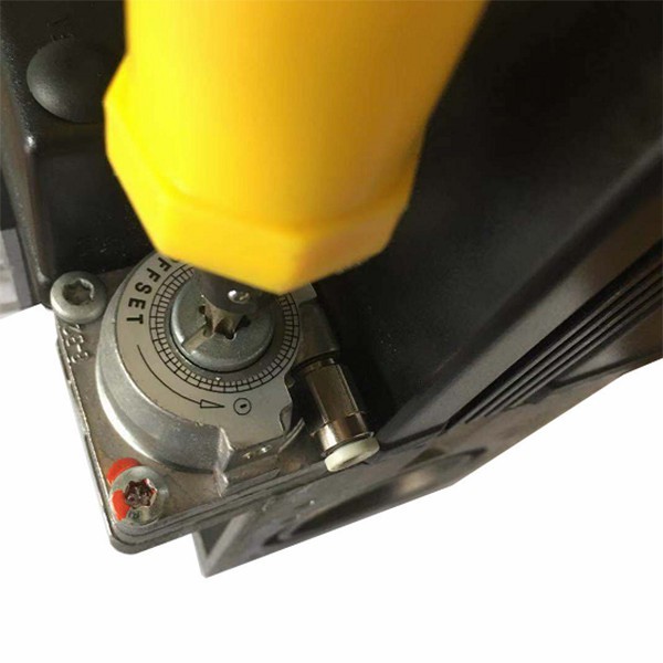
• Turning the screw (white) clockwise increases the outlet pressure.
• Turn the screw (white) counterclockwise to reduce the outlet pressure.
• Ensure that the outlet pressure is properly adjusted before resetting the protection cap.
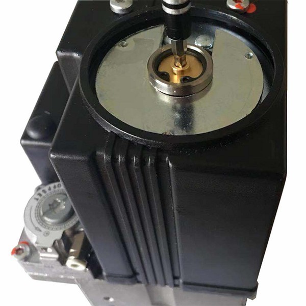
Adjust the main gas flow throttle valve
• Turn the screw (metallic color) clockwise to reduce the gas flow.
• Turn the screw (metallic color) counterclockwise to increase the gas flow.
Installation Precautions
Main gas supply pipe connection
• To avoid distortion and damage to the external piping, ensure that the pipes are not over-tensioned during assembly.
• Ensure the gasket is installed in the correct position.
• Ensure that the gas flow direction matches the arrow indicator on the valve body.
Stress test point
• The valve is equipped with inlet and outlet pressure test ports.
• During testing, loosen the pressure-tap screw by half a turn and then insert the pressure-feedback tube into the pressure tap.
Attention Ensure that the pressure-port sealing screw is tightened after testing.
Electrical Connection
Warning
Disconnect the power supply before making electrical connections. Wiring must comply with local regulatory requirements. The supplier’s instructions must be followed.
• Connect the power supply using the required pins (refer to “Functions”).
• Cables and connectors connected to the terminal valve shall operate normally at a temperature of 105°C.
Inspection and Installation
• After any adjustments, run several complete operating cycles to ensure that all components are functioning properly. Installation Precautions
• Before commissioning the equipment, verify that the wiring is functioning properly.
Service Notes
Important Matters
• Any replaced component must be re-inspected to ensure proper circuit operation.
• When any component is replaced, the wiring and all safety functions shall be inspected.
Perform operations in accordance with the equipment manufacturer’s service and maintenance manual.
Gas Leak Test
• Use factory test equipment to check for gas valve leaks. This test shall be performed only on the valve connected to the main burner. Technical Data
Regular data
Model TGV725
Installation Location Install at any angle
Applicable Gases Class II and Class III Gases
Import pressure
Maximum 100 mbar Operating voltage
220VAC, 50/60 Hz Voltage range Between 85% and 110% of the rated voltage
Cut-off valve rated power 18W
Rated current for actuation of the shut-off valve 100mA
Coil insulation class Class F insulation material
Protection Level IP40 (including optional plug)
Imported filter No. 60 Fine Filter Mesh
Operating temperature environment -15 to -60°C
Regulatory ability Minimum air flow: 0.31 m³/h
Outlet pressure range 0–15 mbar
Valve Type
- The first safety valve
-Second safety valve
EN126/EN161
Category A
Category A
Regulator Type
Class C EN88 Safety shut-off valve closing time
T≤1s Coil temperature rise
△T=60℃ Pressure control connection method
4mm outer diameter trachea Weight
Approximately 4600 g Technical Data
Environmental Conditions
Storage
Climate conditions
Mechanical condition
Temperature range
Humidity
DIN EN 60 721-3-1
Category 1K3
Category 1M2
-30...+70℃
<95% r.h.
Transportation
Climate conditions
Mechanical condition
Temperature range
Humidity
DIN EN 60 721-3-2
Category 2K2
Category 2M2
-15...+60℃
<95% r.h.
Operation
Climate conditions
Mechanical condition
Temperature range
Humidity
DIN EN 60 721-3-3
Category 3K5
3M Category 2
0...+60℃
-15…+60℃ (if required)
<95% r.h.
 Condensed and frozen water are not permitted to enter the valve!
 Function
Plug-in pin connection
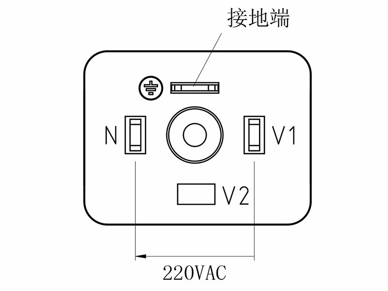
Note:
The TGV725 gas valve’s safety shut-off solenoid coil is of the DC type.
Function
Sectional view
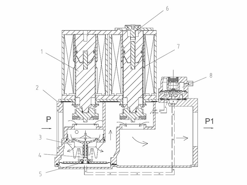
Legend
1 Main Safety Shut-off Valve (Class A)
2 Main Valve Body
3 Proportional Components
4 Throttle Orifice
5 Proportional Control Diaphragm
6 Limit screw
7 Second shut-off valve
8 Gas/Air Regulator
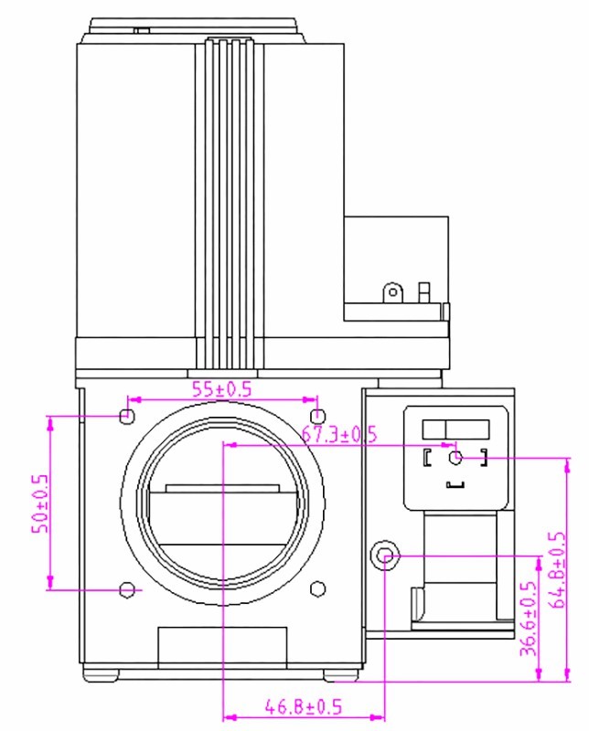
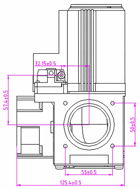
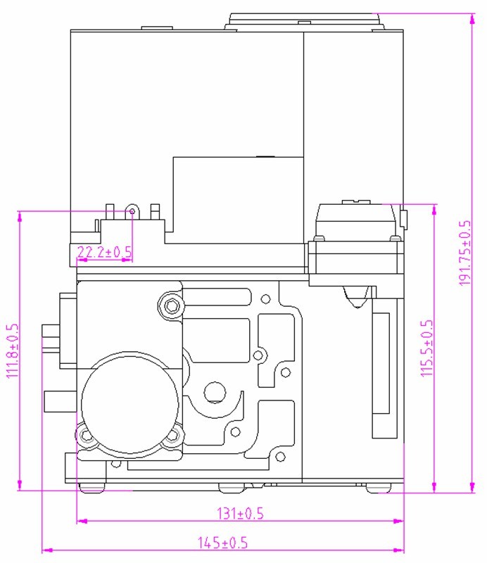
Size
In millimeters
 Keywords:
- 燃气阀


Leave a Message Online
Please note: Kindly provide your email address, and our specialists will contact you as soon as possible!
Address: No. 11 Tengda Road, Cao’e Subdistrict, Shangyu District, Shaoxing City
Phone:+86-575-82052228
Fax:+86-575-82569559
Leave a Message Online


Copyright © Shaoxing Telong Electric Co., Ltd.
Website Development:China Enterprise Dynamics Shaoxing