Seach in this website


Product Series
TGV310

Support hotline:
Category:
Gas Control Valve
- Product Description
-
- Commodity name: TGV310
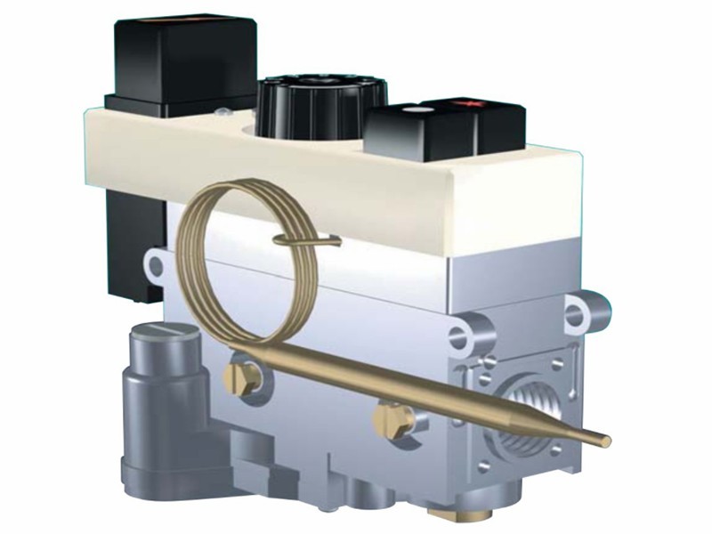
The TGV310 is suitable for use with stoves, boilers,catering equipment and room heaters.
Application
• The TGV310 is suitable for use with stoves, boilers,catering equipment and room heaters.
General data
• Construction characteristics
• Auminium alloy body
• Inline inlet and outlet (straight and elbow flange available)
• Bottom outlet (optional)
• Pilot gas rate adjuster
• Pressure regulator or as an alternative flow adjuster
• Inlet and outlet pressure test points (optional)
• Inlet and pilot filters
• Piezo-electric igniter (optional)
• Four mounting holes
Main features
• Thermoelectric flame supervision device.
• Pressure regulator
• Temperature control
Reference standard
• En126
• Multifunctional device for gas burning appliances
Flow rate q as a function of pressure △P
Gas family Q △P I d=0.45 3.9 m³/h 5 mbar II d=0.6 3.5 m³/h 5 mbar III d=1.7 4.4 m³/h 5 mbar 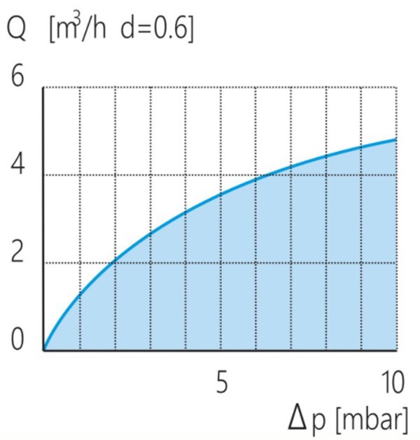
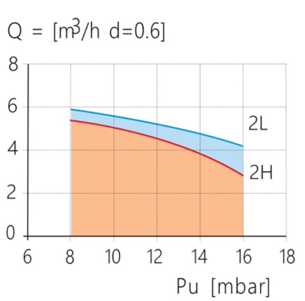
Regulated flow rate Q
Inlet pressure range (mbar)
Gas family Nominal Maximum Minimum 2H 20 25 17 2L 25 30 20 Outlet pressure tolerance +10% -15%
Dimensional dranwing
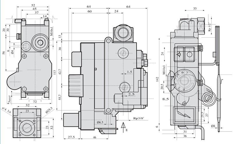
1. lgnition button 7. Maximum flow setting screw
(versions with flow adjuster)
13. Gas inlet 2. Shut-down button 8. Oulet pressure setting screw
(versions with pressure regulator)
14. Main gas outlet 3. Piezo-electric ignition button (optional) 9. Inlet pressure test point 15. Bottom gas outlet 4. Temperature setting knob 10. Outlet pressure test point 16. Flange fixing holes 5. Pilot flow setting screw 11. Thermocouple connection 17. Mounting holes 6. Minimum flow setting screw 12. Pilot outlet 18. Thermostat bulb 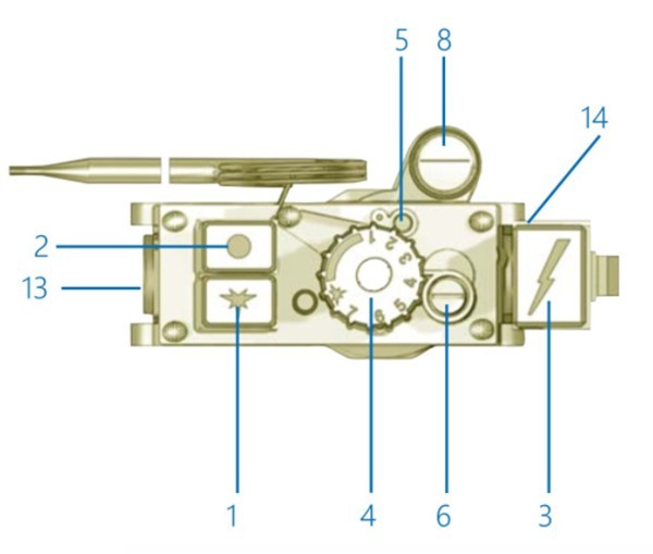
Fig.3: version with pressure regulator
and piezo-electric igniter.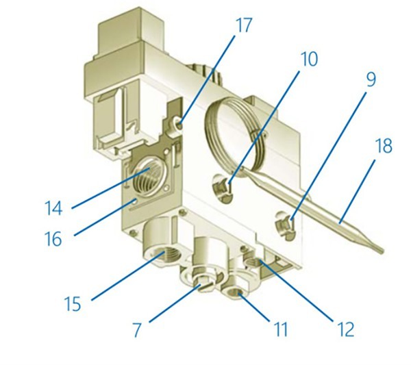
Fig. 4: version with flow adjuster
and piezo-electric igniter.Thermostat data

Use specifications
Mounting position
Gas families
Ambient temperature
Maximum inlet pressure
Bending and torsion resistance
any
I, II and III
0...80℃
50 mbar
Group 2
Mechanical connections
Gas inlet and outlet
Pilot outlet
Thermocouple connection
Pressure test point
Flange fixing holes
Mounting holes
Rp½ or Rp3/8 ISO 7
M10x1 for tube φ 6, φ 4mm, φ1/4
M9x1 or M10x1
φ 9mm
M4 x 7mm
φ 6.5 mm
Flame supervision
Number of cycles expected : > 10000
Lgnition time : < 10s
Shut-off time : < 60s
Pressure regulation
Direct pressure regulator: Class B
Outlet pressure setting range(optional): 3... 1 8mbar(15...30mbar)
Valve Description
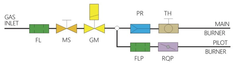
Fig.1: Version with pressure regulator
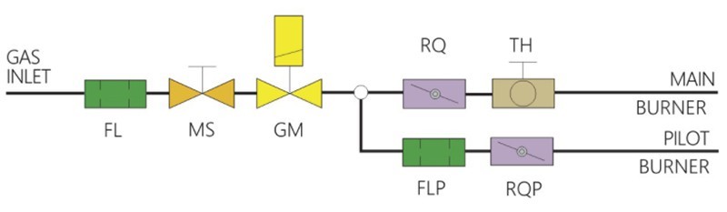
Fig.2: Version with flow adjuster
• FL is the inlet filter
• MS is the operation push button
• GM is the thermoelectric flame supe-rvisior device
• FLP is the pilot filter
• RQP is the pilot flow adjuster
• PR is the pressure regulator
• RQ is the main gas flow adjuster
• TH is the modulating thermostat with on/off function with temperature selecting knobKeywords:- Gas Control Valve


Add:No.11 Tengda Road,Shangyu Econimic Decelopment Zone,Shaoxing City,Zhejiang Province,China.
Tel:+86-575-82052228
Fax:+86-575-82569559
ONLINE MESSAGE